One of the easiest ways to gain 20 to 30 horsepower is to purchase ported and polished aftermarket cylinder heads. The engine will love the upgrade but your wallet may not. Today's aftermarket cylinder heads come with a high price tag.
To alleviate some of the financial pressure, you can send your cylinder head to a machine shop for the porting and polishing job, but that will be expensive. The best way to save the most money while reaping the same performance benefits is to invest your own personal time into porting and polishing the cylinder head yourself.
The porting and polishing process is broadly the same for all cylinder heads. Below we will provide an easy guide to port and polish cylinder heads properly, safely, and efficiently. However, please keep in mind that everything suggested in this article is performed at your own risk. It is very easy to grind way too much metal, which is irreversible and will likely deem the cylinder head unusable.
- Note: If you have little to no experience with a Dremel it is suggested you practice on a spare cylinder head first. Old, spare cylinder heads can be purchased at a salvage yard or a shop may be willing to let you have an old one for free.
Part 1 of 6: Prepping for the job
Materials Needed
- 2-3 cans of brake cleaner
- Scotch-Brite pads
Work gloves
Tip: This entire process will take some time. Possibly 15 labor hours or more. Please remain patient and exercise determination during this procedure.
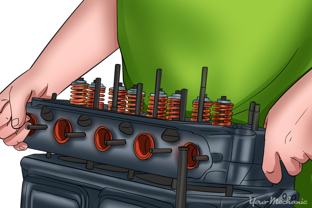
Step 1: Remove the cylinder head. This process will vary from engine to engine, so you should consult your manual for all the details.
Generally, you’ll need to remove any parts from the head obstructing removal and you will need to remove the nuts and bolts securing the head.
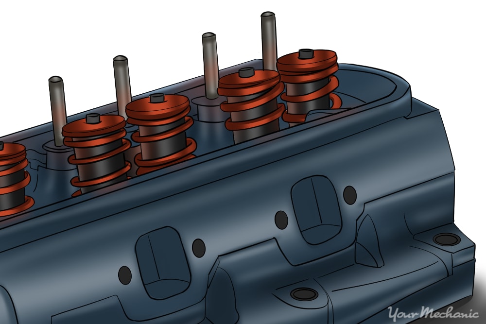
Step 2: Remove the camshaft, rocker arms, valve springs, retainers, valves and lifters. You should refer to your manual for the specifics on removing these as each car is very different.
- Tip: Each component removed should be reinstalled exactly in the position it was removed from. When disassembling, order the removed components in a fashion where you can easily keep track of the original positions.
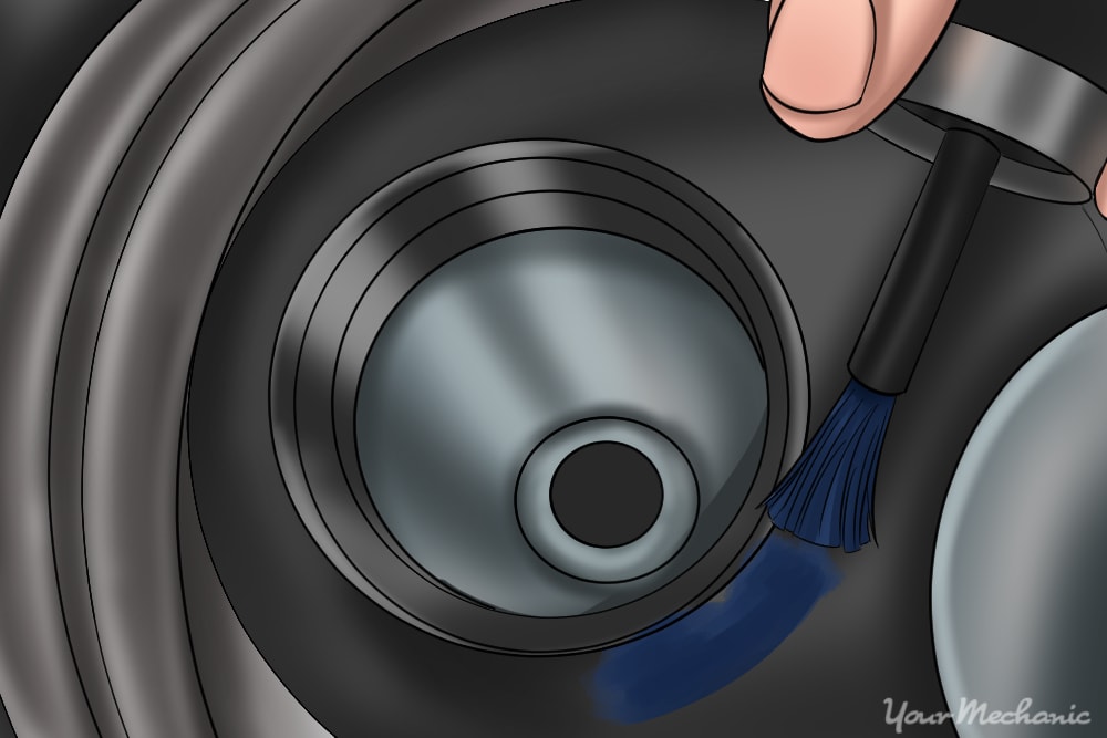
Step 3: Thoroughly clean the cylinder head of oil and debris with brake clean. Scrub with a golden haired wire brush or Scotch-Brite pad to help remove any stubborn deposits.
Step 4: Inspect the cylinder head for cracks. Most commonly they will appear between adjacent valve seats.
- Tip: If a crack is found in the cylinder head the cylinder head must be replaced.
Step 5: Scrub the connection point. Use a Scotch-Brite pad or 80 grit sandpaper to scrub the area where the cylinder head mates with the intake gasket down to bare metal.
Part 2 of 6: Increase airflow
- Dykem Machinist
- Golden haired wire brush
- High speed Dremel (10,000+ RPM capable)
- Lapping tool
- Lapping compound
- Penetrating oil
- Porting and polishing kit
- Safety glasses
- Small screwdriver or other metallic pointed utensil
- Surgical masks or other form of respiratory protection
- Work gloves
- Zip ties
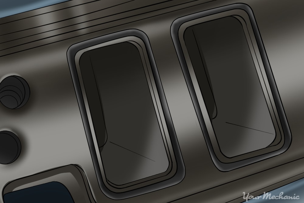
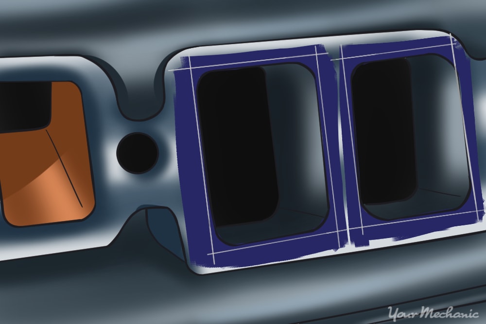
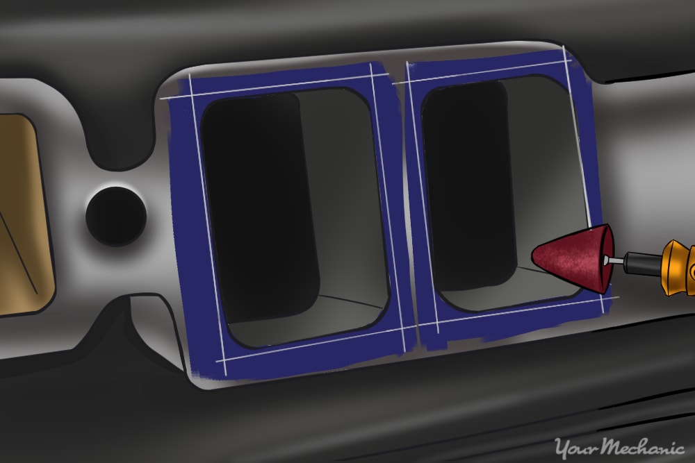
Step 1: Match the intake ports to the intake gaskets. With intake manifold gasket pressed against the cylinder head you can see how much metal can be removed to increase airflow.
The intake runner can be widened much more to match the circumference of the intake gasket.
Step 2: Paint the perimeter of the intake runner with machinist red or blue. After paint dries mate the intake manifold gasket back to the cylinder head.
Use an intake manifold bolt or tape to help hold the gasket in place.
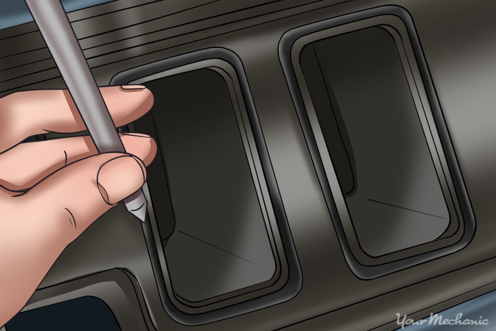
Step 3: Trace around the intake runner. Use a small screwdriver or similar pin pointed object to scribe or trace off the areas around the intake runner where paint is visible.
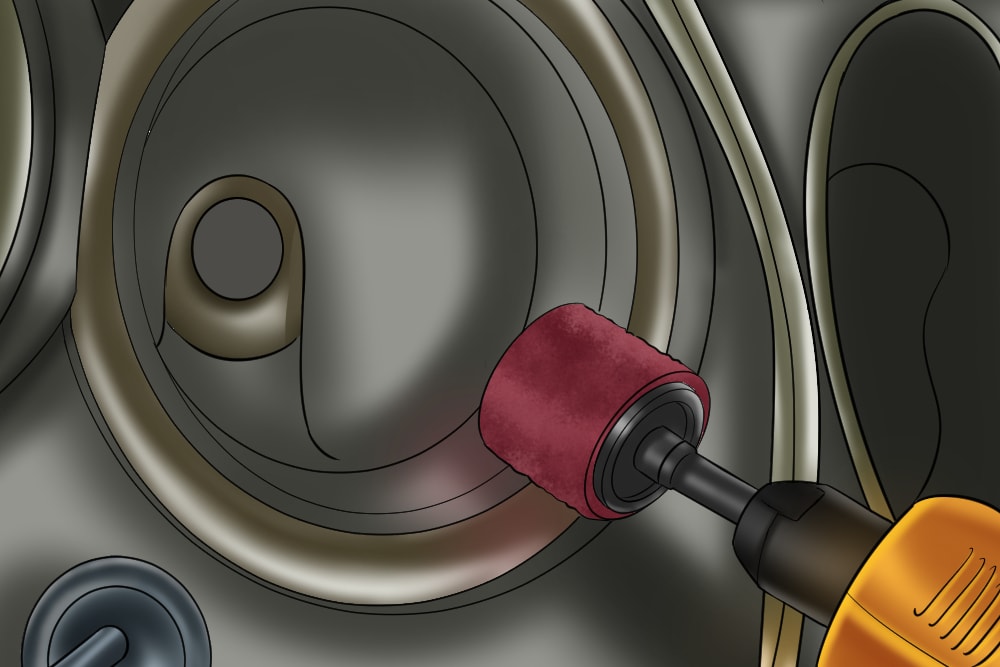
Step 4: Remove the material inside the scribe marks. Use the arrowhead stone bit to remove material inside the scribe marks moderately.
The arrow headstone bit will leave a rough finish, so be extremely careful not to over enlarge the port or mistakenly grind into the area that extends into the intake gasket coverage area.
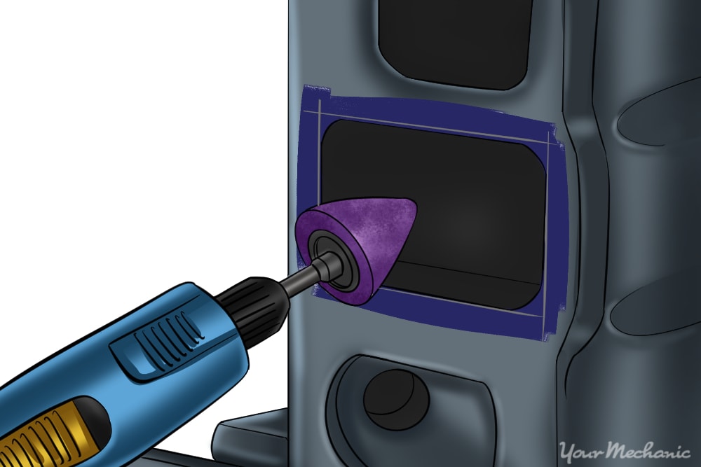
Enlarge the intake runner evenly and uniformly. No need to go too deep inside the runner. It is only necessary to port about an inch to one and a half inches into the intake runner.
Keep the Dremel speed regulated at about 10,000 RPM or you will wear down the bits faster. Take into account the factory RPM of the Dremel you are using to help determine how much faster or slower the RPM must be adjusted to reach the 10,000 range.
For example, if the Dremel you are using has a factory RPM of 11,000 it’s safe to say that you can run it at full throttle without burning out your bits. On the other hand, if the Dremel has a factory RPM of 20,000, then hold the throttle about halfway to a point only where the Dremel operates at about half the speed.
- Warning: Do not remove metal extending into the coverage area of the gasket otherwise a leak may occur.
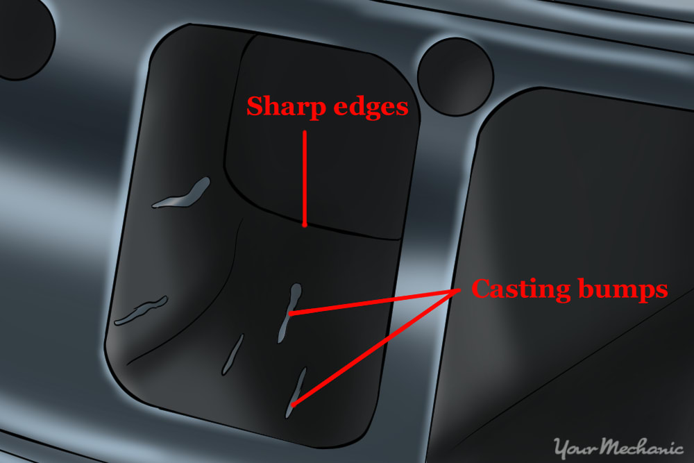
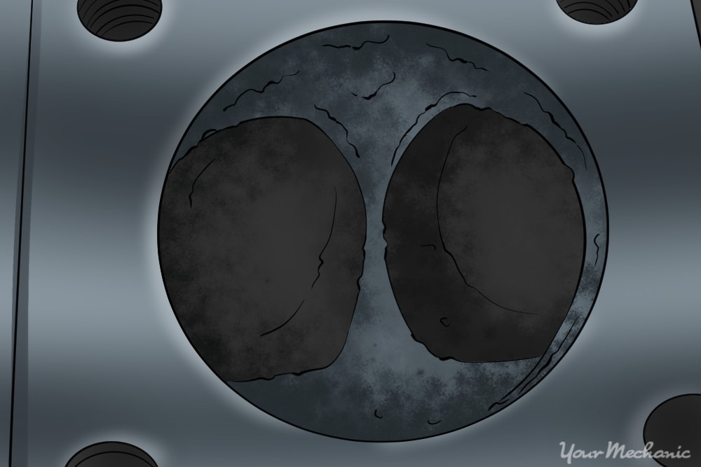
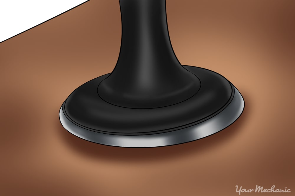
Tip: Grind away any sharp turns, crevices, valleys, rough casting, and casting bumps inside of the intake runner where possible. Refer to the following image for an example of casting bumps and sharp edges.
Tip: Be sure to enlarge the port evenly and uniformly. Once the first runner is enlarged use a cut wire hanger to help gauge the enlargement process. Cut the hanger in a length that is in reference to the width of the first ported exhaust runner. Therefore, you can use the cut hanger as a gauge to get a better idea of how far the other runners must be enlarged. Each intake runner enlargement should be about equal to one another so they can flow the same volume. The same rule applies for the exhaust runners also.
Step 4: Smooth out the new surface area. Once the entry port is enlarged use the less coarse cartridge rolls to smooth out the new surface area.
Use a 40 grit cartridge to do most of the grinding then use a 80 grit cartridge to get a nice smooth finish.
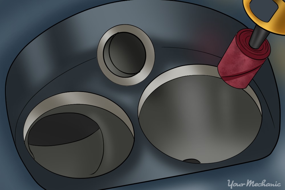
Step 5: Inspect the intake runners. Place the cylinder head bottom side upward and inspect the inside of the intake runners through the valve holes.
Step 6: Remove any obvious unevenness. Grind away any sharp turns, crevices, valleys, rough casting, and casting bumps using the cartridges.
Use a 40 grit cartridge to uniformly port the intake runner. Emphasize on removing any imperfections. Then use a 80 grit cartridge to further smoothen the ported area.
- Tip: When grinding be extremely careful not to grind any areas where the valve would officially make contact with the cylinder head, also known as the valve seat, or a new valve job will be the result.
Step 7: Complete the other intake runners. After finishing the first intake runner move on to the second intake runner, third and so on.
Part 3 of 6: Porting the exhaust
Without porting the exhaust side too the engine will not have enough displacement to allow the increased air volume to efficiently exit. To port the exhaust side of the engine the steps are very much the same.
- Dykem Machinist
- Golden haired wire brush
- High speed Dremel (10,000+ RPM capable)
- Penetrating oil
- Porting and polishing kit
- Safety glasses
- Small screwdriver or other metallic pointed utensil
- Surgical masks or other form of respiratory protection
- Work gloves
Step 1: Scrub the mating area. Use Scotch-Brite pad to scrub the area where the cylinder head mates with the exhaust gasket down to bare metal.
Step 2: Paint the perimeter of the exhaust runner with machinist red or blue. After paint dries mate the exhaust manifold gasket back to the cylinder head.
Use an exhaust manifold bolt or tape to help hold the gasket in place.
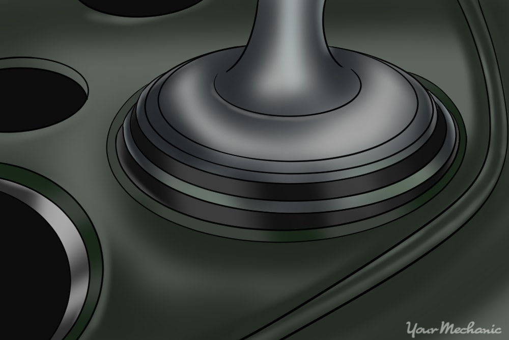
Step 3: Scribe out the areas where paint is visible with a very small screwdriver or similar pin pointed object. Use the images in Step 9 as references if needed.
Grind away any rough casting or casting bumps because the carbon deposits could easily collect on spots left unchecked and cause turbulence.
Step 4: Enlarge the port opening to match the scribe marks. Use the Arrowhead stone bit to do most of the grinding.
- Note: The arrowhead stone bit will leave a rough finish, so it may not look as you would expect just yet.
- Tip: Be sure to enlarge the port evenly and uniformly. Once the first runner is enlarged use the cut wire hanger technique mentioned above to help gauge the enlargement process.
Step 5: Port the exhaust runner enlargement using the cartridges. This will give you a nice smooth finish.
Start with a 40 grit cartridge to do most of the conditioning. After working the surface thoroughly with the 40 grit cartridge, use a 80 grit cartridge to get a nice rippleless finish.
Step 6: Continue on the remaining exhaust runners. Once the first exhaust runner inlet is properly ported repeat these steps for the remaining exhaust runners.
Step 7: Inspect the exhaust runners. Place the cylinder head bottom side upward and inspect the inside of the exhaust runners through the valve holes for imperfections.
Step 8: Remove any roughness or imperfections. Grind away any sharp turns, crevices, valleys, rough casting, and casting bumps.
Use a 40 grit cartridge to uniformly port the exhaust runner. Emphasize on removing any imperfections, then use a 80 grit cartridge to further smoothen the ported area.
Warning: As stated before, be very careful not to mistakenly grind any of the areas where the valve would officially make contact with the cylinder head, also known as the valve seat, or extreme irreversible damage may occur.
Tip: After using the steel carbide bit, switch to a less coarse cartridge roll to further smoothen the surface where needed
Step 9: Repeat for the remaining exhaust runners. Once the end of the first exhaust runner is properly ported repeat for the remaining exhaust runners.
Part 4 of 6: Polishing
- Dykem Machinist
- Golden haired wire brush
- High speed Dremel (10,000+ RPM capable)
- Penetrating oil
- Porting and polishing kit
- Safety glasses
- Small screwdriver or other metallic pointed utensil
- Surgical masks or other form of respiratory protection
- Work gloves
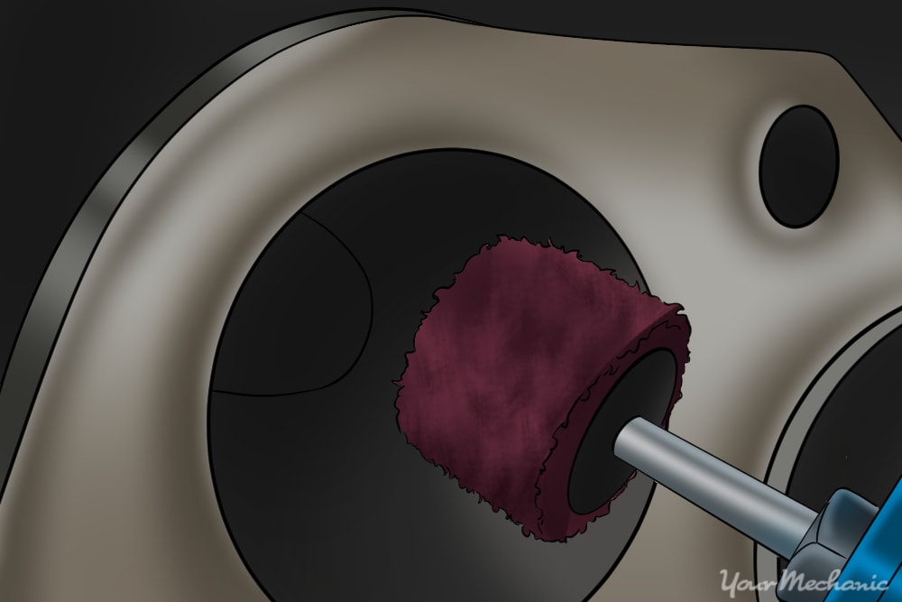
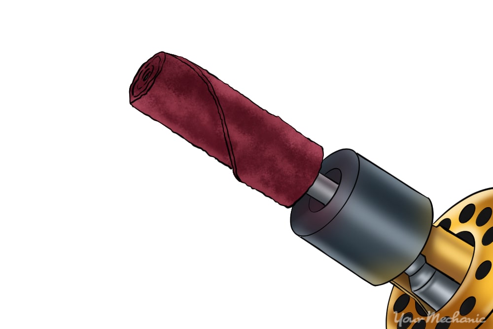
Step 1: Polish the inside of the runner. Use the flapper from the porting and polishing kit to polish the inside of the runner.
You should see an increase and shine as you move the flapper across the surface. It is only necessary to polish up to about an inch to an inch and a half inside of the intake runner. Polish the intake runner uniformly before moving on to the next buffer.
- Tip: Remember to keep your Dremel speed at about 10000 RPM to maximize the lifespan of the bits.
Step 2: Use the medium grit cross-buffer. Repeat the same process as above but use the medium grit cross-buffer instead of the flapper.
Step 3: Use a fine-grit cross buffer. Repeat the same process again but use a fine grit cross-buffer for the final finish.
It is recommended to spray buffer and runner in small increments with WD-40 to help bring out a gleaming and shimmering finish.
Step 4: Complete for the remaining runners. After the first intake runner is successfully polished move on to the second intake runner, third and so on.
Step 5: Polish the exhaust runners. When all of the intake runners are polished proceed to polish the exhaust runners.
Polish each exhaust runner using the exact same guidelines and buffer sequence provided in the above steps.
Step 6: Polish the outlets of the runners. Place the cylinder head bottom side up so we can polish the outlets of the intake and exhaust runners.
Step 7: Apply the same buffer sequence. To polish the outlets of both the intake and exhaust runners apply the same buffer sequence that was previously used.
Use the flapper for the first stage of polishing, then a medium-grit cross buffer for the second stage, and fine-grit cross buffer for the final polish. In some cases the flapper may not fit into tight areas. If so, use the medium-grit cross buffer to port the areas the flapper is unable to reach.
- Tip: Don't forget to spray WD-40 in small increments while using the fine-grit cross buffer to further illustrate a shine.
Step 8: Focus on the bottom portion of the cylinder head. Now let’s really focus on porting and polishing the bottom portion of the cylinder head.
The goal here is to eliminate rough surfacing that could cause pre ignition and clean carbon deposits. Place the valves in their original locations to protect the valve seats while porting.
Part 4 of 6: Polish the cylinder deck and chamber
- Dykem Machinist
- High speed Dremel (10,000+ RPM capable)
- Penetrating oil
- Porting and polishing kit
- Safety glasses
- Small screwdriver or other metallic pointed utensil
- Surgical masks or other form of respiratory protection
- Work gloves
- Zip ties
Step 1: Use the cartridge rolls to smooth the area where the chamber meets the deck. Tie zip ties around the valve stem to help secure the valves in place.
The 80 grit cartridge should be adequate for this stage of porting. Perform this step on each cylinder deck and chamber.
Step 2: Polish the cylinder deck. Once each cylinder deck has been ported we will polish them using almost all the same techniques as before.
This time polish using only using the fine-grit cross buffer. At this point you should really start to see the cylinder head twinkle. To really make the cylinder head shine bright like a diamond use the fine-grit cross buffer to bring out the final sparkle.
Tip: Remember to keep your Dremel speed at about 10000 RPM to maximize the lifespan of the bits.
Tip: Don't forget to spray WD-40 in small increments while using the fine-grit cross buffer to further illustrate a shine.
Part 6 of 6: Complete valve lapping
- Dykem Machinist
- Lapping tool
- Lapping compound
- Surgical masks or other form of respiratory protection
- Work gloves
Next, we will recondition your valve seats safely. This reconditioning process is known as valve lapping.
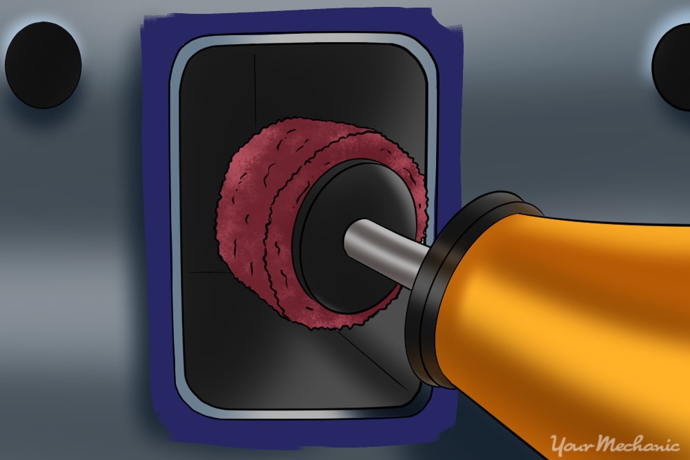
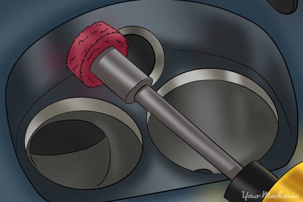
Step 1: Paint the perimeter of the valve seats with machinist blue red or blue. The paint will help visualize the lapping pattern and indicate when the lapping is complete.
Step 2: Apply the compound. Apply the lapping compound to the base of the valve.
Step 3: Apply the lapping tool. Put the valve back into the original location and apply the lapping tool.
With a little pressure spin the lapping tool between your hands at a fast pace like warming your hands or as if you are trying to start a fire.

Step 4: Inspect the pattern. After a few seconds pull the valve from the seat and inspect the pattern you made.
If the valve and seat have developed a shiny ring, your job is done and you can move on to the next valve and valve seat. If not there's a good chance you have a bent valve that will need to be replaced.
Step 5: Reinstall any pieces that you removed. Reinstall the camshaft, rocker arms, valve springs, retainers and lifters.
Step 6: Reinstall the cylinder head. When finished double check the timing before starting the vehicle.
All that time spent buffing, polishing, grinding, and lapping has paid off. To verify the performance results, take the cylinder head to a machine shop and have it flow bench tested. The test will expose any leaks and allow you to see the volume of air flow transiting the runners. You want the volume transiting each intake runner to be very similar. If you have any questions about the process, Ask a Mechanic for some quick and helpful advice, and be sure to have your cylinder head temperature sensor replaced if needed.