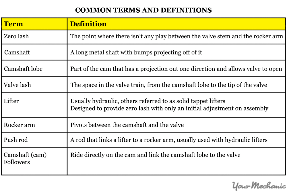
The term “valve adjustment” is an oxymoron. What is actually being adjusted is the clearance between the linkage of the camshaft and the valve. It is most often called the valve lash. This system that links the camshaft to the valve comes in many designs. All of them require adjustment when first assembled, but some are virtually maintenance free after their initial adjustment. Each system has its strengths and weaknesses in both performance and its maintenance cycles. This article will help you to inspect the valve and have a valve clearance adjustment as needed.
Part 1 of 7: Understand your system
- Note: The list of tools below are a complete list to adjust any type of valve system. Refer to Part 3, Step 2 for the specific tool needed for the style of valve system you will be working on.
Part 2 of 7: Determine whether your car needs a valve adjustment
Material Needed
Step 1: Listen for valve noise. The need for valve adjustment is determined by their sound.
More accurately, the louder the tapping made in the valve train, the greater the need for adjustment. Properly adjusted valve lash will be quiet. Some systems will always have a light tapping noise, but should never be so loud as to overshadow all the other noises the motor makes.
-
Note: Knowing when the valves are too loud is a matter of experience. Not to mention, they very gradually become louder and we are often oblivious to this fact. If you're not sure, find someone with experience to help you determine the need for adjustment.
Step 2: Determine where the noise is coming from. If you have determined your valves need adjustment, you can either adjust them all, or you can only adjust the ones that need it.
Motors with two heads, such as with a V6 or V8, will have two sets of valves. Use a stethoscope and take some time to pinpoint the problem valve by identifying the loudest one.
Part 3 of 7: Removing the valve cover or covers
Materials Needed
- Ratchet and socket
- Screwdriver
Step 1: Remove any components mounted above or to the valve cover or covers. This could be wiring harnesses, hoses, pipes or an intake plenum.
You don’t need to completely remove all of this from the car. You just need to make enough room for the valve cover to be removed from the head and to gain access to the valve adjusters.
Step 2: Unscrew the valve cover bolts or nuts. Turn the bolts or nuts counterclockwise to remove them.
Make sure you have removed them all. They are often hidden in unsuspecting spots.
Tip: Often there is a buildup of dirt caked oil that hides the valve cover bolts or nuts. Be sure to remove this buildup to thoroughly inspect the valve cover for what retains it.
Tip: Valve cover bolts and nuts are usually mounted around the outer edge, but often there will be a few nuts or bolts mounted in the middle of the valve cover. Be sure to thoroughly inspect for all of them.
Step 3: Gently but firmly pry the valve cover away from the head. Often the valve cover is glued to the head and will require some extra force to remove it.
This will require you to find a safe strong area to pry on the valve cover. You can use a flat head screwdriver and wedge it between the valve cover and the head and gently pry it away or you can use a pry bar as a lever and do the same from another location.
- Warning: Take care not to break the valve cover. Do not use excessive force. Often times it will take continued gentle prying in multiple spots before the valve cover will give way. If you feel you are prying too hard, you probably are.
Part 4 of 7: Identify the type of valve adjustment system your car has.
Step 1: Determine which type of valve lash adjusters your car has. If you are not sure after reading the following descriptions, you will need to refer to the appropriate repair manual.
A hydraulic self-adjusting style of valve lash system is hydraulic and only requires you to set the initial preload. The self adjusting is achieved with the use of a hydraulic lifter that is charged by the oil pressure system of the motor.
The term “solid tappet” is often used to describe a non-hydraulic lifter, but is mainly a reference to a valve train that is not hydraulic. The solid tappet design may or may not utilize lifters. Some have rocker arms and others use cam followers. Non-hydraulic valve trains require adjustment on a regular schedule to maintain proper valve lash.
A cam follower simply rides directly on the camshaft lobe; it follows the cam. It can be in the form of a rocker arm or lifter. The differences between a lifter and a cam follower are often semantic.
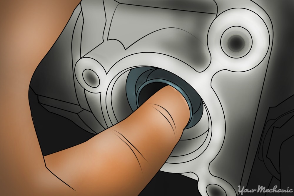
The Toyota puck style cam follower is very efficient until the need for adjustment. Adjusting the puck style cam follower requires replacing spacers mounted in the cam follower, which is an extensive process.
Fine measurements are required and usually multiple steps of disassembly and reassembly are required to get it right. The pucks or spacers are purchased individually or as a kit from Toyota and can be quite expensive. For this reason, many people will neglect this style of valve adjustment.
Step 2: Determine which tools you need to adjust your particular system. All except a hydraulic system will require a feeler gauge.
The hydraulic lifter system will require the correct size socket and ratchet.
The solid tappet will require feeler gauges, the correct size wrench, and a flat head screwdriver. Cam followers require the same as the solid tappet. They are essentially the same type of system.
Toyota puck style solid tappets require feeler gauges, a micrometer, and the tools to remove the camshaft and the timing belt or chain. For instruction on the camshaft, timing belt or timing chain removal, refer to your repair manual.
Part 5 of 7: Checking and or adjusting the valves for a non-hydraulic type
Materials Needed
- Correct size box end wrench
- Feeler gauges
- Micrometer
Note: Part 5 applies to both cam follower and solid tappet designs.
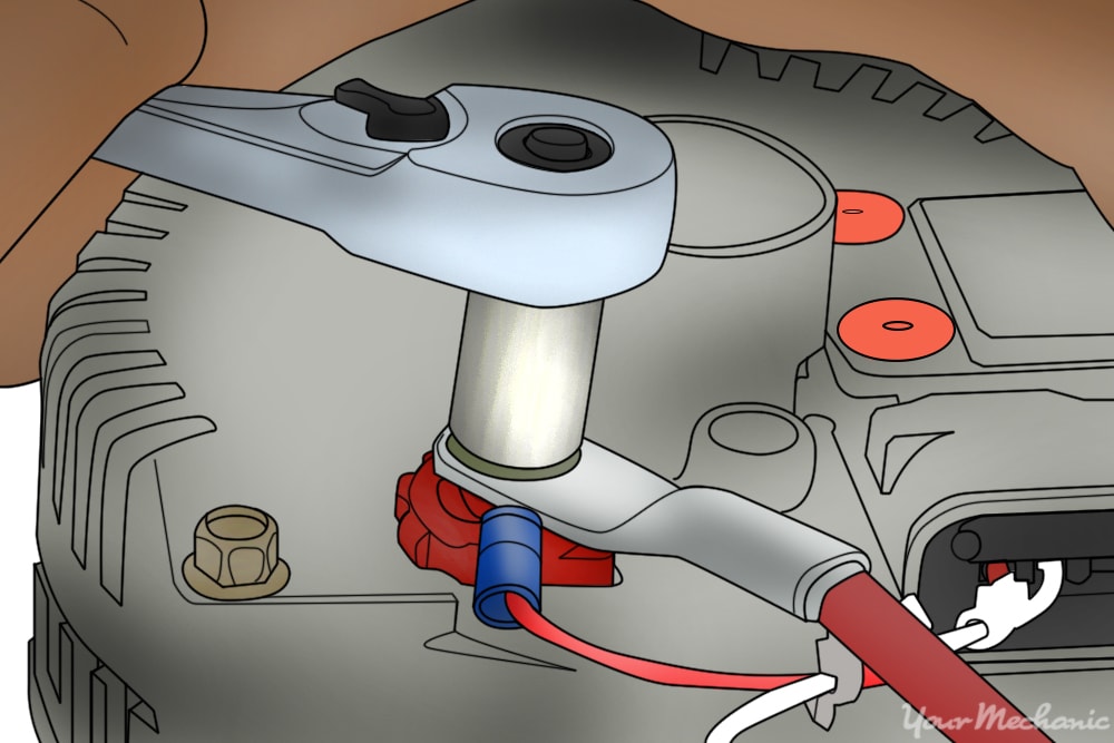
Step 1: Connect your remote starter switch. First connect your remote starter switch to the smaller wire on the starter solenoid.
If you're not sure which wire is the exciter wire, you will need to refer to a wiring diagram in your repair manual to be sure. Connect the other wire of the remote starter switch to the positive side of the battery.
If your starter exciter wire is not accessible, you will need to turn the motor over by hand with a ratchet or wrench on the crankshaft bolt. Many vehicles will have a remote solenoid on the fender well that you can connect the remote starter switch to.
It will always be easier to use a remote switch, but you will need to evaluate the effort involved to connect it versus the effort to turn the motor over by hand.
Step 2: Look up the correct valve lash gap from your owners manual. Often this specification can be found under the hood of your car on the emissions sticker or another sticker.
There will be an exhaust and an intake specification.
Step 3: Position the first set of valves in the closed position. Position the camshaft lobes that contact the rocker arm or cam followers directly opposite the nose of the cam lobe.
Note: It is vitally important the valves are in the closed position when adjusting the valves. They cannot be adjusted in any other position.
Tip: The most accurate way to check valve clearance is to check it at three places on the low side of the cam lobe. It is referred to as the base circle of the cam lobe. You want to check this space with a feeler gauge at the center of the base circle and to each side of it before it begins to ramp up toward the nose. Some vehicles are more sensitive to this adjustment than others. Often you can get away with just checking it at the center of the base circle, but some motors are best checked at the three points outlined above.
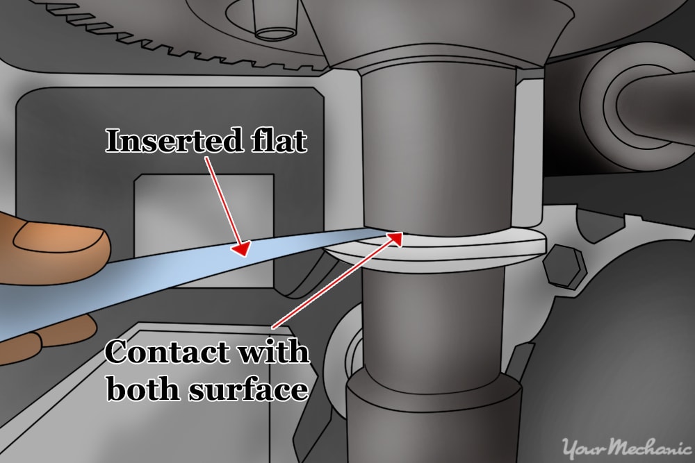
Step 4: Insert the correct feeler gauge. This will occur either at the camshaft lobe or the top of that valve.
Taking this measurement at the camshaft will always be the most accurate, but often it isn’t possible to access the camshaft lobe.
Step 5: Move the feeler gauge in and out to get a feel for how tight the adjustment is. The feeler gauge should not slide too easily but should not be so tight that moving it is difficult.
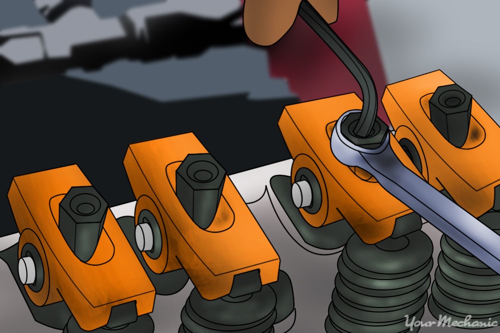
If it is too tight or too loose, you will need to release the lock nut and turn the adjuster in the necessary direction to tighten or loosen it.
Step 6: Tighten the lock nut. Make sure to hold the adjuster with the screw driver.
Step 7: Check the clearance with the feeler gauge again. Do this after you have tightened the lock nut.
Often the adjuster will move during the tightening of the lock nut. If it does, repeat steps 4-7 again until the clearance feel correct with the feeler gauge.
- Tip: The feel of the feeler gauge should be firm but not tight. If it falls out of the clearance space easily, it is too loose. The more accurate you are with this, the quieter the valves will be when finished. Take more time during the first few valves to gauge the feel of a properly adjusted valve. Once you get it, you will be able to go through the rest of them more quickly. Every vehicle will be a little different, so don’t expect them all to be the same.
Step 8: Reposition the camshaft to the next valve. This can be the next in the firing order or the next inline on the camshaft.
Determine which method is the most time efficient and follow that pattern for the rest of the valves.
Step 9: Repeat steps 3-8. Do this until all the valves are adjusted to the correct clearance.
Step 10: Install the valve covers. Be sure to install any other components you may have removed as well.
Part 6 of 7: Hydraulic lifter adjustment
Materials Needed
- Correct size box end wrench
- Feeler gauges
- Micrometer
- Remote starter switch
Step 1: Determine the correct lifter preload for the motor you are working on. You will need to refer to the repair manual for your year make and model for this specification.
Step 2: Position the first valve in its closed position. Use the remote starter to do this or turn the motor by hand.
Step 3: Turn the adjusting nut clockwise until you reach zero lash. Refer to the definitions above for zero lash.
Step 4: Turn the nut the additional amount as specified by the manufacturer. This can be as little as a quarter turn or as much as two turns.
The most common preload is one turn or 360 degrees.
Step 5: Use the remote starter switch to position the next valve in its closed position. You can follow the firing order or each valve as it come inline on the camshaft.
Step 6: Install the valve cover. Be sure to install any other components you may have removed.
Part 7 of 7: Adjusting the Toyota solid tappet lifter
Material Needed
- Correct size box end wrench
Step 1: Determine the correct valve lash. There will be a different valve lash clearance range for the intake and the exhaust valves.
Step 2: Measure the valve lash of each valve before disassembly. Take extra care when making this measurement.
It needs to be as accurate as possible and should be measured in the same fashion as the solid tappet systems outlined above.
Step 3: Subtract the manufacturer’s specification amount from the actual measured amount. Keep track of which valve it is for and record the difference.
You will add the difference to the size of the original lifter if the clearance is out of specification.
Step 4: Remove the camshaft from the head. Do this if you have found some valves not within the manufacturer's specification.
This will require the removal of the timing belt or the timing chain. Refer to the appropriate repair manual for instruction during this part of the procedure.
Step 5: Mark all the cam followers by location. Indicate the cylinder number, intake or exhaust valve.
Step 6: Remove the cam followers from the head. Earlier designs have a separate puck that can be removed from the follower or lifter as some refer to it.
Newer designs require the lifter itself to be measured and replaced if it is out of specification.
Step 7: Measure the thickness of the lifter or the inserted puck. If the clearance of the valve is out of specification, add the difference between the actual clearance and the manufacturer’s specification.
The value you calculate will be the thickness of the lifter you will need to order.
- Note It is vitally important your measurements are as accurate as possible because of the extensive nature of the disassembly and reassembly of the camshaft. Keep in mind, measurements on this scale must take into account an error factor, determined by how tight or loose the feeler gauge is when checking the valve lash.
Step 8: Install the valve cover. Be sure to reinstall any other components you may have removed.
Each system has its strengths and weaknesses. Be sure to study the design of the car you are working on thoroughly. If you have any questions about the process, Ask a Mechanic for some detailed and helpful advice or consult a certified mechanic from YourMechanic to have a valve clearance adjustment performed.